MCE backplane protocol
This document describes the bus backplane communication protocol used by cards in the MCE subrack to communicate with each other.
Contents
Physical layer
The 25Mbps asynchronous serial communication link over the bus backplane is carried out over 1 multi-drop LVDS pair from Clock Card to other cards (star-link) and point-to-point LVDS pairs from every Address card, bias card, and readout card back to the Clock Cards for a total of 16 pairs for a full-size 72-HP subrack or 12 pairs for a 48-HP subrack. A 25MHz sync clock is generated on the clock card and distributed to all cards over a backplane LVDS pair. On each card, the sync clock is fed to a PLL to generate the receiver clock.
Data link layer
The backplane communication follows the command-response model where communication is always initiated by CC. The multi-drop line is used to issue commands to other cards. Each card sends a reply back on one of its 2 dedicated LVDS pairs to CC. The other pair is currently unused. A receiver will align itself with the transmitter at the beginning of every 32-bit word, using a start bit. While the receiver is receiving, its clock will deviate from the transmit clock. However, because the length of the transmitted word is short (32 bits), the clock does not deviate far enough to get out of sync with the transmit clock. All packets over the backplane, moving in either direction (to and from CC), have the same format. A 2-byte preamble of 0xAAAA marks the start of a packet and is used to synchronize the receiver and the transmitter. A CRC checksum is used to check the integrity of the data. The packet has a data portion that can be of variable length. For packets originating from the clock card (commands), the destination card is encoded in the packet. For reply packets originating on cards other than the CC and transmitted over the point-to-point line, the packet-source is encoded in the packet. There is no guarantee that a reply packet is generated for each command packet. No redundancy or retransmission is built into the protocol. Instead, the clock card has an internal timeout mechanism to deal with cases when no reply is received. The receiver ignores the packet if a valid preamble is not detected. A packet is pronounced invalid if the checksum is wrong, but a reply is sent back regardless.
Packet structure
A backplane packet consists of a variable number of 32-bit words. Transmission is little-ended (bit 0 first). The packet is structured like this:
| Word offset | Value | |||||||||||||||||||||||||||||||
|---|---|---|---|---|---|---|---|---|---|---|---|---|---|---|---|---|---|---|---|---|---|---|---|---|---|---|---|---|---|---|---|---|
| Bit | 31 | 30 | 29 | 28 | 27 | 26 | 25 | 24 | 23 | 22 | 21 | 20 | 19 | 18 | 17 | 16 | 15 | 14 | 13 | 12 | 11 | 10 | 9 | 8 | 7 | 6 | 5 | 4 | 3 | 2 | 1 | 0 |
| 0 | 0xAA | 0xAA | reserved | Virt | Rd/Wr | Data size (n) | ||||||||||||||||||||||||||
| 1 | card ID | param ID | reserved | Cmd Failed | CRC err | |||||||||||||||||||||||||||
| 2 | data[0] | |||||||||||||||||||||||||||||||
| ... | ... | |||||||||||||||||||||||||||||||
| 1+n | data[n] | |||||||||||||||||||||||||||||||
| 2+n | CRC checksum | |||||||||||||||||||||||||||||||
- Preamble (bits 31 to 16 of word 0) is 0xAAAA, which is used for synchronization. (Note: because the data are transmitted little-ended, this isn't actually the frist 16-bits sent.)
- Virt (bit 12 of word 0), is 1 when the command is virtual (sent to an upper card ID), 0 otherwise (version 6 firmware only)
- Rd/Wr (bit 11 of word 0) is 0 for a read (RB) or 1 for a write (WB)
- Data size (bits 10 to 0 of word 0) specifies the packet size. Eleven bits are allocated to specify size of the payload in terms of 32-bit words (excluding card address/status/checksum words). Therefore, a backplane packet may contain up to 211−1=2047 words of data. However, the largest backplane packet a full frame of data transmitted from a single Readout Card to the Clock Card (64×8=512 words with version 6 firmware).
- Card ID and Param ID (bits 31 to 16 of word 1) specify the destination parameter for commands (from the clock card) or the origin parameter for replies (to the clock card)
- Status bits (bits 15 to 0 of word 1). Only two bits are defined: bit 0 indicates a CRC error in the incoming command packet, bit 1 indicates that the command execution failed.
Backplane-to-fibre packet translation
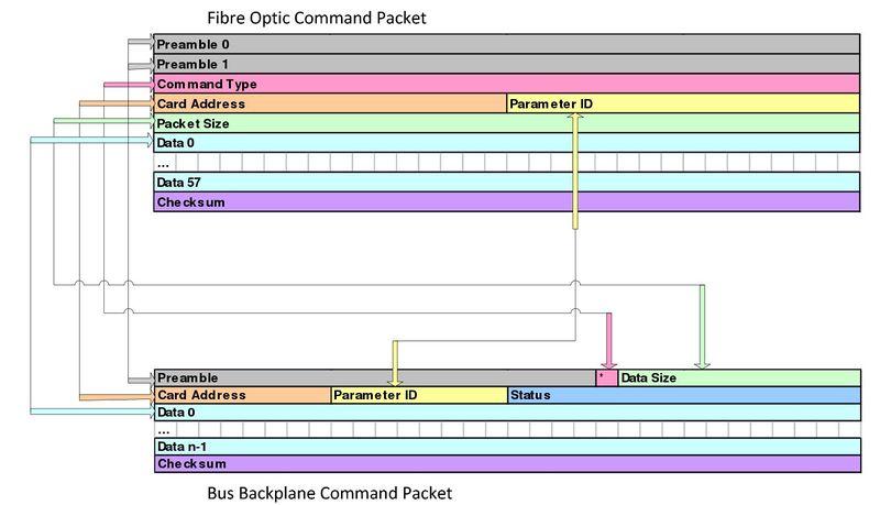
The following figure shows the correlation between backplane packets and MCE fibre protocol command packets.
Legacy documents
The following document is the original MCE communications protocol description from which this document is descended. It does not discuss any changes made after 2012 (including the version 6 firmware). It also contains information on the MCE fibre protocol (as well as the Clock Card–PSUC communications protocol, which is now obsolete).
