Sync Box
The Sync Box generates a data-valid pulse along with a sequential 32-bit number to synchronize the data-acquisition operation of up-to 8 MCE subracks and other housekeeping equipment. The 32-bit number can be used to stamp all collected data points. The Sync Box has 8 fibre outputs to connect to the MCE subracks and few TTL/RS485 outputs to be used by other housekeeping equipment. User commands are input to the Sync Box via RS-232. The CPLD generates a serial bit stream which is Manchester encoded with a 25MHz clock, and contains information for occurrences of address_zero, data_valid, and also a frame sequence number.
Contents
Specifications
Power consumption
Excluding the fibre transmitters, the sync box consumes 1.35W. Each fibre transmitter (Avago HFBR-1119TZ) consumes 185mA x 5V = 0.925W, so a sync box with all eight tranmitters populated consumes 8.75W. To minimise power consumption, only the required number of transmitters should be populated. Input power is either 5V or 24V, depending on configuration.
Approximate dimensions
- Size
- 5cm × 20cm × 25cm
- Weight
- 600 grams
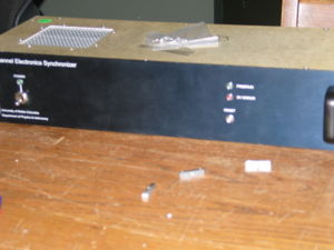
The obsolete, rack-mount AC-in sync box was 2U (9cm) × 19 inches (48cm) × 21cm deep and weighed 1.9kg.
External connectors and I/O
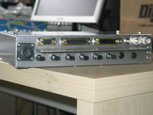
- These are the connectors and pinout for the DC-in sync box. For the connector pinout of the obsolete AC-in sync box, see Sync Box AC-in Rack Mount I/O.
CP1: DC power in
Different connectors are used for 5V and 24V input.
- 5V
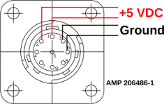
- Box connector is an AMP 206486-1. +5VDC on pins 1 and 2. Return on pins 3 and 6. Other pins not populated. Pins 3 and 6 are connected to sync box ground.
- mating connector on the power brick is: AMP 206485-1
- 24V
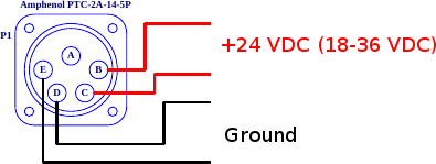
- Box connector is an Amphenol PT-2A-14-5P. +24VDC on pins B and C. Return on pins D and E. Pin A is not connected. Unlike the 5V-in sync box, the 24V-in sync box isolates pins D and E from sync box ground.
CJ2: RS-232 command port
A nine pin DE-9F provides the serial command port. See RS-232 communication and commanding below for details. The only lines wired through to the Atmel processor are:
| Pin | Signal |
|---|---|
| 2 | TxD |
| 3 | RxD |
| 4 | DSR |
| 5 | GND |
Don't rely on DSR. Assume no hardware or software flow control.
CJ3: Digital I/O
A twenty five pin DB-25F is used for digital I/O. Pins 1, 2, and 14 are inputs. All other pins are outputs. All grounds, including pin 14, are connected in the sync box to sync box ground.
In RTS mode, any falling edge of Data_Valid will be taken as a RTS DV signal. In Free Run mode, this input is ignored.
There are two pairs of RS485 outputs which provide a NRZ and clock version of the DV sync word. Data_Sync_1 and Data_Sync_4 have the clock and Data_Sync_2 and Data_Sync_3 have the NRZ sync word. There are also TTL versions of Data_sync_3 and Data_Sync_4.
Note: the output contains only the DV sync word, not the single-zero-bit ARZ occurrences between DVs. For firmware versions before 1f, the clock rate is fixed at 5MHz. Later versions allow changing the clock rate by setting a divisor, d, with the ckd command. In these versions the clock rate is 50MHz ÷ d. The default value of d is 10 (meaning the default clock rate remains 5MHz).
| Pin | Signal | Pin | Signal |
|---|---|---|---|
| 1 | Data_Valid RS485− | ||
| 14 | GND | ||
| 2 | Data_Valid RS485+ | ||
| 15 | Data_Sync_1 RS485− | ||
| 3 | GND | ||
| 16 | Data_Sync_1 RS485+ | ||
| 4 | Data_Sync_2 RS485− | ||
| 17 | GND | ||
| 5 | Data_Sync_2 RS485+ | ||
| 18 | Data_Sync_3 RS485− | ||
| 6 | GND | ||
| 19 | Data_Sync_3 RS485+ | ||
| 7 | Data_Sync_3 TTL | ||
| 20 | GND | ||
| 8 | GND | ||
| 21 | Data_Sync_4 RS485− | ||
| 9 | Data_Sync_4 TTL | ||
| 22 | Data_Sync_4 RS485+ | ||
| 10 | N/C | ||
| 23 | GND | ||
| 11 | N/C | ||
| 24 | N/C | ||
| 12 | N/C | ||
| 25 | N/C | ||
| 13 | N/C | ||
CP4: ACDCU
- Note: to make full use of these, firmware updates are needed.
The ACDCU connector is a DB-25M. It can be used for general purpose I/O. Originally, these lines were used to control associated AC-DC Units, which are no longer in production. In most cases, this connector is left unpopulated. All grounds are connected in the sync box to sync box ground. The ps command will read these lines and report them as a hex-encoded byte:
Synco> ps
       ACDCU_Status = 0X7B
The dpu, dpa, epa, and pof commands can be used to control them.
| Pin | Signal | Pin | Signal |
|---|---|---|---|
| 1 | Aux_in_1 | ||
| 14 | GND | ||
| 2 | Aux_out_1 | ||
| 15 | Aux_in_2 | ||
| 3 | GND | ||
| 16 | Aux_out_2 | ||
| 4 | Aux_in_3 | ||
| 17 | GND | ||
| 5 | Aux_out_3 | ||
| 18 | Aux_in_4 | ||
| 6 | GND | ||
| 19 | Aux_out_4 | ||
| 7 | Aux_in_5 | ||
| 20 | GND | ||
| 8 | Aux_out_5 | ||
| 21 | Aux_in_6 | ||
| 9 | GND | ||
| 22 | Aux_out_6 | ||
| 10 | Aux_in_7 | ||
| 23 | GND | ||
| 11 | Aux_out_7 | ||
| 24 | Aux_in_8 | ||
| 12 | GND | ||
| 25 | Aux_out_8 | ||
| 13 | N/C | ||
CJ5: TTL in
A female BNC used to provide an external TTL clock. The line is 50-ohm terminated. Ground (outer conductor) is connected to sync box ground. Note: this input is currently ignored in firmware.
CJ6: TTL out
A female BNC providing a NRZ version of the output stream. The line is 50-ohm terminated. Ground (outer conductor) is connected to sync box ground.
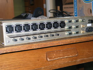
MCE0 through MCE7: Fibre outputs
There are up to eight fibre-optic outputs (some which may not be populated to reduce power consumption). These outputs are connected to MCE Clock Card sync-in connection. The fibre-optic outputs are divided into two groups of four each, which allow the possibility for dual-rate operation. All outputs provide the Manchester-encoded output stream.
Reset button
Pressing the reset momentary switch restarts the sync box control program and resets all parameters to their default values.
Front panel LEDs
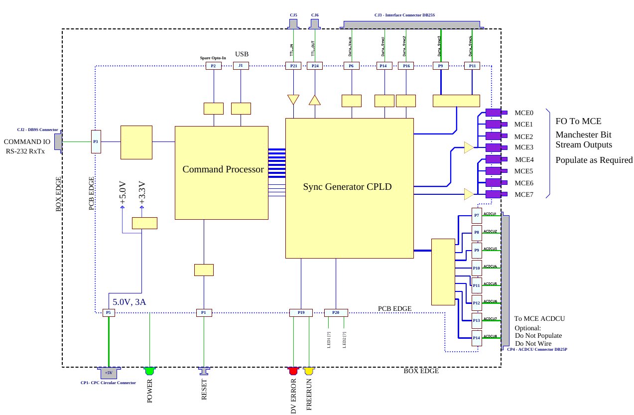
- Power (green): The power LED is on whenever the sync box is powered on. Note: because the power for this LED is teed off of the power wiring harness (see schematic above), in cases where P5 has become disconnected, with external power applied, this lamp will be lit without the sync box actually being powered.
- Free run (yellow): The free-run LED is on whenever the sync box is in free-run mode.
- DV error (red): The DV error LED is turned on whenever more than one RTS DV pulse is received between successive address-reutrns-to-zero (ARZs); see The Manchester output stream below. It is turned off at the next ARZ. This cannot occur in free-run mode.
Schematics
Here is a box diagram of the 5VDC-in sync box. The 24VDC-in sync box includes a 24-to-5V DC-DC converter module between the front panel power connector (CP1) and P5 on the sync board. The obsolete AC-in sync box also uses the same sync board, but has different external connections.
Documents
- Sync Board Schematics (S589-101)
- Block Diagram:
- Wiring Diagrams
RTS mode vs Free-run mode
The sync box operates either in free-run mode (the default) or else RTS mode. When in free-run mode, the sync box generates its own data valid (DV) triggers by down-counting occurrences of address-return-to-zero (ARZ), which occur at a rate of 25MHz × row_len × num_rows. The data_rate parameter to fr indicates how many ARZ occurrences occur between successive DVs.
In RTS mode, data_rate is ignored. Instead, the sync box waits for a falling edge on the Data_Valid RS485 digital input. When a falling edge is detected, a DV will be output on the next ARZ. If multiple falling edges are detected before an ARZ, only a single DV will be issued. (That is: only one external DV trigger is honoured per ARZ.)
These days, almost everyone uses free-run mode.
The Manchester output stream
By default, the Manchester output bit-stream encodes simply the 25MHz clock as a series of (Manchester-encoded) one bits. Exceptions to this are:
- Address-Return-to-Zero (ARZ): Occurrences of ARZ are encoded into the Manchester bit-stream as a single binary zero. ARZ occurs at a rate of 25MHz × row_len × num_rows, regardless of operating mode (free-run or RTS).
- Data Valid sync word: This is a 40-bit sequence which is output on certain ARZ occurrences. In free-run mode, the data_rate parameter indicates the number of ARZs between successive DV sync word output. In RTS mode, it can be output on every ARZ, but only if a RTS DV pulse has arrived since the last ARZ. On ARZs where the DV sync word is not output, only the ARZ bit will be zero (all other bits will be 1).
- The 40-bit DV sync word looks like this; bit zero is sent first:
 zd-fe--- Nnnnnnnn nnnnnnnn nnnnnnnn nnnnnnnn
 0        0        1        2        3
 0        8        6        4        2
- where:
- z is the address-return-to-zero (ARZ) bit (always zero)
- d is the data valid bit (always zero)
- - are reserved (unused) sync-word status bits
- f is one when operating in free-run mode and zero when in RTS mode
- e is the dv_error bit. It is one if in RTS mode and more than one RTS DV pulse was received since the last ARZ. Zero otherwise (including always zero in free-run mode).
- Nnn... is the 32-bit frame sequence number. The most significant bit (N) is sent first.
Firmware
- See: Sync Box Firmware
The sync box program comes in two parts: a program that runs on the Atmel microcontroller, and another that runs on the CPLD. For information on how to obtain the firmware, how to reprogram your sync box, and access to the source code, see Sync Box Firmware.
RS-232 communication and commanding
Commands are sent to the Sync Box over a 9600 baud RS-232 link, with no hardware or software flow control, connected to an Atmel AT89C5131A-M, an 8-bit, 80C51-compatible single-chip microcontroller. Input command variables are checked by the command processor and loaded one byte at a time into the sync generator CPLD over programmed I/O connections with eight bits for data and an eight-bit address.
Text returned by the sync box over RS232 use carriage return for line termination. Most Linux users will need to tell minicom (or whatever serial terminal they use) to add line feeds to avoid all output being overwritten on the same line.
More than one command may be put on a single input command line, up to a maximum of 12 tokens (commands + arguments), and 80 characters.
Command summary
The sync box responds to the following commands over the RS-232 link:
| Command | Description | Default | FW Version |
|---|---|---|---|
| h | Help: print a list of commands. | — | all |
| ? | Shows the current sync box parameters and status. | ||
| rl n | Set row_len to n where 1 ≤ n ≤ 4095 NB: Because the sync box clock is 25MHz, this value should be half the value of the corresponding MCE row_len. For example, to have a row_len of 100 on the MCE, set this value to 50. Also, row_len × num_rows must be ≥ 250. |
64 | ≤ 1f |
| 53 | 20, 21 | ||
| 50 | ≥ 22 | ||
| nr n | Set num_rows to n where 1 ≤ n ≤ 63 Note: row_len × num_rows must be ≥ 250. |
41 | ≤ 1f |
| 33 | ≥ 20 | ||
| rt | Enable RTS mode (turn off free-run mode). | Off | all |
| fr [n] | Enable free-run mode (turn off RTS mode) and set data_rate to n where 1 ≤ n ≤ 4095. If n is omitted, the previously commanded value for data_rate is re-used. | 47 | ≤ 1f |
| 120 | 20, 21 | ||
| 38 | ≥ 22 | ||
| fn n | Set frame sequence number to n where 0 ≤ n ≤ 232−1 | — | all |
| ckd n | Set the clock divisor to n where 1 ≤ n ≤ 255. The NRZ output clock is 50MHz ÷ n. Before version 1f, the divisor is fixed at 10 (5MHz clock). | 10 | ≥ 1f |
| go | Enable Manchester and DV outputs. | On | all |
| st | Disable Manchester and DV outputs. | ||
| dpa | Disable all power outputs. | All on | |
| dpu n | Disable power output n where 0 ≤ n ≤ 7 | ||
| epu n | Enable power output n where 0 ≤ n ≤ 7 | ||
| pof | Get ACDCU on/off control byte | — | |
| ps | Get ACDCU status byte | ||
| bank n | Change target MCE bank for commands. n=0 for both (unbanked); n=1 for low bank (MCE1–4); n=2 for high bank (MCE5–8) | 0 | ≥ 31 |
| eeprom | Enter EEPROM manipulation mode | — | |
| re | Reset sync box to default state. | all | |
EEPROM manipulation mode | |||
| Note: this menu is activated by the eeprom command from the main menu. | |||
| h | Help: print a list of EEPROM manipulation mode commands. | — | ≥ 31 |
| exit | Leave EEPROM manipulation mode and return to the main menu. | ||
| dump | Dump the contents of the EEPROM. | ||
| load | Load the Sync Box configuration saved to the EEPROM, overwriting the currently-running configuration. | ||
| save | Save the currently-running Sync Box configuration to the EEPROM. | ||
| enable_boot | Load the saved configuration from the EEPROM on boot. | Off | |
| disable_boot | Don't load the configuration saved to EEPROM on boot. Instead, the baked-in default configuration hard-coded in the code will be used. | ||
Status output
The ? command produces output similar to this:
Synco> ?
Mancho_Enable = ON
DV_Mode = FreeRun_DV
Frun_Count = 47
Row_len = 64
Num_Row = 41
ACDCU_onoff = 0X00
Command error messages
Some example error messages:
Synco> xx       WHAT? "xx"      // Unrecognised command
Synco> rl 9999  TOO BIG "9999"  // Parameter too large
Synco> rl 0     TOO SMALL "0"   // Parameter too small
Synco> rl xx    WHAT? "xx"      // Parameter could not be parsed
Using minicom in Linux
To issue commands to a Sync Box over an RS-232 line, you can use a Linux program called minicom. To install this application, do:
sudo apt-get install minicom
To start MiniCom:
sudo minicom
Minicom needs the following options changed for it to work properly:
<ctrl-a>, <z>, <a> (to turn on line feeds)
<ctrl-a>, <z>, <o>, <Serial port setup> <Serial Device> = /dev/ttyS0
<ctrl-a>, <z>, <o>, <Serial port setup> <Bps/Par/Bits> = 9600 8N1
<ctrl-a>, <z>, <o>, <Serial port setup> <Hardware Flow Control> = No
<ctrl-a>, <z>, <o>, <Serial port setup> <Software Flow Control> = No
<ctrl-a>, <z>, <o>, <Modem and dialing> <Modem has DCD line> = No
After you modify these settings, remember to save, exit, and restart Minicom.
Enabling sync box use in the MCE
To check that the sync box is connected correctly to the MCE, issue the command
wb cc select_clk 1
and then read back the value:
rb cc select_clk
Line   0 : ok : 1
Setting select_clk to 1 tells the MCE to sync its internal clock with the clock signal encoded from the sync box. If the MCE does not see the sync box, the parameter will revert to zero (internal clock) in about one second.
To accept sync triggers and serial numbers from the sync box, two more commands are needed:
wb cc use_sync 2
wb cc use_dv 2
These registers are configured automatically by the config system if the parameters hardware_sync=1 and config_sync=1 in experiment.cfg. If you change the values in $MAS_DATA/experiment.cfg instead of $MAS_CONFIG/experiment.cfg, remember to run mce_make_config before re-running the config script.
Also be sure that you have the correct mce.cfg file. A quick way to check that sync numbers are getting into the MCE frame data is to take some frames and check the data using the eat_packets tool:
$  mce_run sync_test 400 s
RUNFILE_NAME=/data/cryo/current_data//sync_test.run
FRAME_BASENAME=/data/cryo/current_data//sync_test

$ eat_packets -n 5424 -f $MAS_DATA/sync_test
Forced     frame_size=1356 (5424)
offset     frm_idx   frame#
0000000000        0        0  surprise sync_dv 4168076, after sequence [0,0)
EOF, exiting after 10000 frames + 0 bytes
If the mce_run does not terminate quickly, the sync box may not be properly connected to the MCE. If eat_packets complains only about the first frame (offset 00000000), then the sync numbers are intact and incrementing contiguously. If eat_packets complains about pretty much every frame, the sync numbers are not being inserted into the frame data.
Legacy documents
- The original "Sync Box User's Guide" is available here:
- http://www.phas.ubc.ca/~mce/mcedocs/hardware/tech_description/SyncBox_UserGuide_S589_502.pdf
- Please note: it is rather out of date (being last updated in 2007), and known to be wrong in places. All relevant information from the guide should be available on this wiki.
