Difference between revisions of "Connector Mating System Maintenance"
From MCEWiki
| (4 intermediate revisions by 2 users not shown) | |||
| Line 1: | Line 1: | ||
| − | [[image:IMG_0978.JPG | 400px |thumb | + | {{Related|Subrack}} |
| − | | Rear view of an MDM ]] | + | {| |
| − | + | |- | |
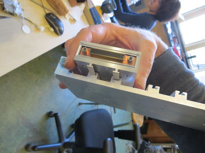
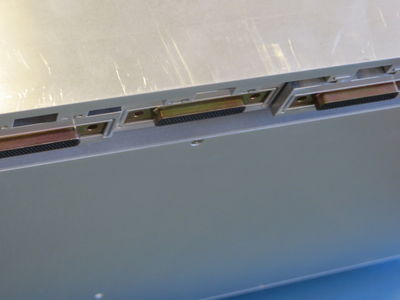
| − | in a filtered housing sitting on rails. A threaded shaft drives this connector towards or away from the cryostat. | + | | [[image:IMG_0978.JPG | 400px |thumb | Rear view of an MDM ]] |
| − | + | | in a filtered housing sitting on rails. A threaded shaft drives this connector towards or away from the cryostat. | |
| − | + | |- | |
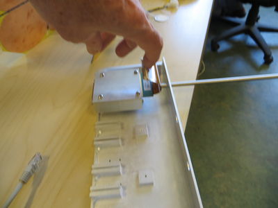
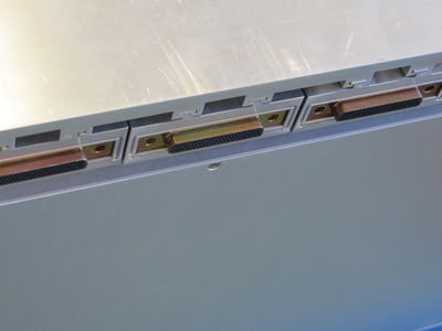
| − | + | | [[image:IMG_0979.JPG| 400px |thumb | Side view of an MDM, upside down. ]] | |
| − | [[image:IMG_0979.JPG| 400px |thumb | + | | The shaft pushes or pulls the filter/connector box w.r.t. the rest of the electronics. The flex electrical connector connects to the backplane. |
| − | | Side view of an MDM, upside down. ]] | + | |- |
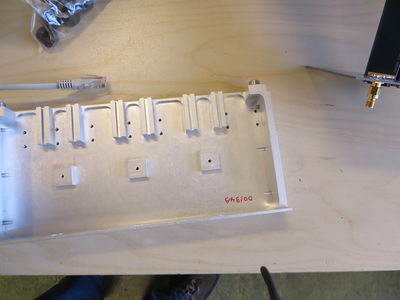
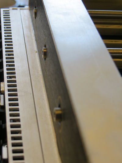
| − | + | | [[image:IMG_0974.JPG| 400px |thumb | Inside view of the housing]] | |
| − | The shaft pushes or pulls the filter/connector box w.r.t. the rest of the electronics. The flex electrical connector connects to the backplane. | + | | Inside view of the housing showing a pair of slots for the rails per MDM and the hole for the bolt which keeps each filter/connector box from moving too far once installed. |
| − | + | |- | |
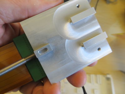
| − | + | | [[image:IMG_0975.JPG| 400px |thumb | Close-up of the base of a filter box ]] | |
| − | + | | This close up shows the rails and also the oval slot used to keep the filter from moving too far. | |
| − | + | |- | |
| − | [[image:IMG_0974.JPG| 400px |thumb | + | | [[image:IMG_0976.JPG| 400px |thumb | Assembly detail ]] |
| − | | Inside view of the housing]] | + | | |
| − | Inside view of the housing showing a pair of slots for the rails per MDM and the hole for the bolt which keeps each filter/connector box from moving too far once installed. | + | |- |
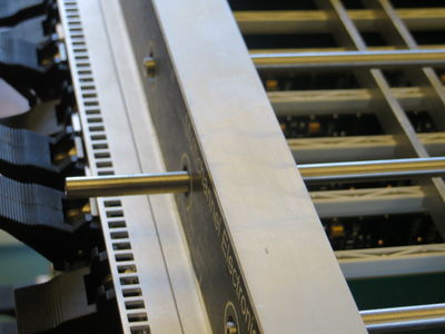
| − | + | | [[image:IMG_0952R.JPG | 400px |thumb | Side view along the front panel ]] | |
| − | + | | showing the hex front ends of all the connector mating shafts. Notice that even when well adjusted there may be small differences in how far each shaft end protrudes. | |
| − | [[image:IMG_0975.JPG| 400px |thumb | + | |- |
| − | | Close-up of the base of a filter box ]] | + | | [[image:IMG_0953.JPG| 400px |thumb | Inside top view of the shafts ]] |
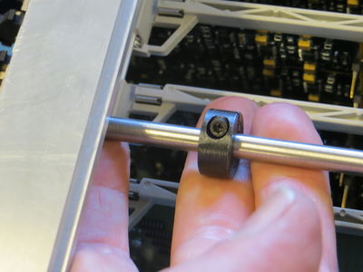
| − | + | | Looking back towards the front panel from above the MCE, see that each shaft is held from moving out of the front of the box by a black steel split clamp. These clamps rest against the front inside of the MCE. The insertion force for the connectors arise in reaction from these clamps pushing on the front of the MCE top panel. | |
| − | This close up shows the rails and also the oval slot used to keep the filter from moving too far. | + | |- |
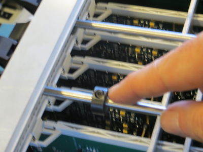
| − | + | | [[image:IMG_0954.JPG| 400px |thumb | Inside view of shafts towards the rear. ]] | |
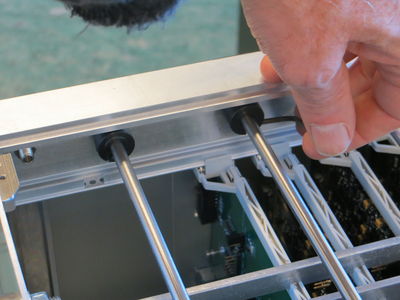
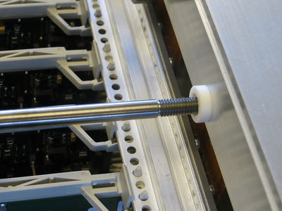
| − | + | | Looking out towards the cryostat, if one iwas present, from above the MCE, see a set of teflon washers and another set of black split-ring clamps. These clamps keep the shafts from moving towards the cryostat. The force to remove a connector from the cryostat arises in reaction to the force these rear rings apply to the housing. Notice also the bolts which serve ae retaining pins for the filter/connector boxes. | |
| − | + | |- | |
| − | [[image:IMG_0976.JPG| 400px |thumb | + | | [[image:IMG_0958.JPG| 400px |thumb | Rear split ring in compression ]] |
| − | | Assembly detail ]] | + | | Pressing the front panel hex heads brings the rear split ring into contact with the teflon washer and the Rear housing. |
| − | + | |- | |
| − | + | | [[image:IMG_0959.JPG| 400px |thumb | Rear slit ring with shaft in tension ]] | |
| − | + | | Pulling on the front of the shaft can open a small gap at the rear before the front split ring come s into tension with the front of the MCE box. A gap of 1mm or so, as seen here, is typical. | |
| − | [[image:IMG_0952R.JPG | 400px |thumb | + | |- |
| − | | Side view along the front panel ]] | + | | [[image:IMG_0960.JPG| 400px |thumb | Step 1 in shaft removal. ]] |
| − | showing the hex front ends of all the connector mating shafts. Notice that even when well adjusted there may be small differences in how far each shaft end protrudes. | + | | To remove or re-position a shaft, first loosen the rear split ring. |
| − | + | |- | |
| − | + | | [[image:IMG_0961.JPG| 400px |thumb | Step 1 continued ]] | |
| − | [[image:IMG_0953.JPG| 400px |thumb | + | | ..and slide it forwards. |
| − | | Inside top view of the shafts ]] | + | |- |
| − | Looking back towards the front panel from above the MCE, see that each shaft is held from moving out of the front of the box by a black steel split clamp. These clamps rest against the front inside of the MCE. The insertion force for the connectors arise in reaction from these clamps pushing on the front of the MCE top panel. | + | | [[image:IMG_0962.JPG| 400px |thumb | Step 2 in shaft removal ]] |
| − | + | | Then, loosen the front split ring. This might be a bit easier if you turn the shaft a few turns to allow the front ring to come away from the front wall. | |
| − | |||
| − | |||
| − | [[image:IMG_0954.JPG| 400px |thumb | ||
| − | | Inside view of shafts towards the rear. ]] | ||
| − | |||
| − | Looking out towards the cryostat, if one iwas present, from above the MCE, see a set of teflon washers and another set of black split-ring clamps. These clamps keep the shafts from moving towards the cryostat. The force to remove a connector from the cryostat arises in reaction to the force these rear rings apply to the housing. Notice also the bolts which serve ae retaining pins for the filter/connector boxes. | ||
| − | |||
| − | |||
| − | |||
| − | [[image:IMG_0958.JPG| 400px |thumb | ||
| − | | Rear split ring in compression ]] | ||
| − | |||
| − | Pressing the front panel hex heads brings the rear split ring into contact with the teflon washer and the Rear housing. | ||
| − | |||
| − | |||
| − | |||
| − | [[image:IMG_0959.JPG| 400px |thumb | ||
| − | | Rear slit ring with shaft in tension ]] | ||
| − | |||
| − | Pulling on the front of the shaft can open a small gap at the rear before the front split ring come s into tension with the front of the MCE box. A gap of 1mm or so, as seen here, is typical. | ||
| − | |||
| − | |||
| − | |||
| − | [[image:IMG_0960.JPG| 400px |thumb | ||
| − | | Step 1 in shaft removal. ]] | ||
| − | |||
| − | To remove or re-position a shaft, first loosen the rear split ring. | ||
| − | |||
| − | |||
| − | [[image:IMG_0961.JPG| 400px |thumb | ||
| − | | Step 1 continued ]] | ||
| − | |||
| − | ..and slide it forwards. | ||
| − | |||
| − | |||
| − | [[image:IMG_0962.JPG| 400px |thumb | ||
| − | | Step 2 in shaft removal ]] | ||
| − | |||
| − | Then, loosen the front split ring. This might be a bit easier if you turn the shaft a few turns to allow the front ring to come away from the front wall. | ||
Victor, who usually does this assembly and who, modestly, does not claim to do anything difficult, says this step requires a little bit of manual dexterity. | Victor, who usually does this assembly and who, modestly, does not claim to do anything difficult, says this step requires a little bit of manual dexterity. | ||
| − | + | |- | |
| − | + | | [[image:IMG_0963.JPG| 400px |thumb | Step 2 Continued...]] | |
| − | + | | ..and slide it towards the back. | |
| − | [[image:IMG_0963.JPG| 400px |thumb | + | |- |
| − | | Step 2 Continued...]] | + | | [[image:IMG_0964.JPG| 400px |thumb | Step 3 in shaft removal]] |
| − | + | | Now you can unthread the shaft and it becomes free to move forward. | |
| − | ..and slide it towards the back. | + | |- |
| − | + | | [[image:IMG_0965.JPG| 400px |thumb | Step 3 , view 2. at rear of MCE ]] | |
| − | + | | Notice that the shaft threads are '''LEFT HANDED!!''' THis is to keep the sense of which way to turn the bolt to tighten the connectors. (You are actually pushing, not pulling.) Remember, the teflon washers and split rings are all still on the shaft. If you are actually removing the shaft try not to drop all the bits down into the cards. | |
| − | [[image:IMG_0964.JPG| 400px |thumb | + | |- |
| − | | Step 3 in shaft removal]] | + | | [[image:IMG_0968.JPG| 400px |thumb | View of connectors from the rear]] |
| − | + | | See that the one of these connectors whose shaft has been partly removed, and whose split-ring clamps have been moved is not alligned with the other MDM connectors. | |
| − | Now you can unthread the shaft and it becomes free to move forward. | + | |- |
| − | + | | [[image:IMG_0969.JPG| 400px |thumb | View of connectors from the rear ]] | |
| − | + | | ..so align it by hand. | |
| − | [[image:IMG_0965.JPG| 400px |thumb | + | |- |
| − | | Step 3 , view 2. at rear of MCE ]] | + | | [[image:IMG_0970R.JPG| 400px |thumb | Front panel during re-assembly ]] |
| − | + | | Thread the shaft into the filter box until you are happy with how the shaft is positioned. | |
| − | Notice that the shaft threads are '''LEFT HANDED!!''' THis is to keep the sense of which way to turn the bolt to tighten the connectors. (You are actually pushing, not pulling.) Remember, the teflon washers and split rings are all still on the shaft. If you are actually removing the shaft try not to drop all the bits down into the cards. | + | |- |
| − | + | | [[image:IMG_0971.JPG| 400px |thumb | Sliding Clamps back home ]] | |
| − | + | | Slide the split ring clamps back where they belong. | |
| − | [[image:IMG_0968.JPG| 400px |thumb | + | |- |
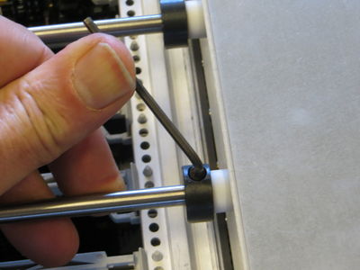
| − | | View of connectors from the rear]] | + | | [[image:IMG_0972.JPG| 400px |thumb | Tightening the rear Split-ring clamp ]] |
| − | + | | ..and tighten them in place. | |
| − | See that the one of these connectors whose shaft has been partly removed, and whose split-ring clamps have been moved is not alligned with the other MDM connectors. | + | |} |
| − | |||
| − | |||
| − | [[image:IMG_0969.JPG| 400px |thumb | ||
| − | | View of connectors from the rear ]] | ||
| − | |||
| − | |||
| − | ..so align it by hand. | ||
| − | |||
| − | |||
| − | |||
| − | [[image:IMG_0970R.JPG| 400px |thumb | ||
| − | | | ||
| − | |||
| − | |||
| − | |||
| − | [[image:IMG_0971.JPG| 400px |thumb | ||
| − | | | ||
| − | |||
| − | |||
| − | |||
| − | [[image:IMG_0972.JPG| 400px |thumb | ||
| − | | | ||
| − | + | [[Category:Subrack]] | |
Latest revision as of 18:18, 31 August 2016
Related topics:
► Hardware
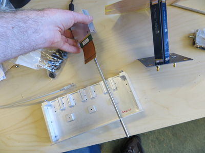
| in a filtered housing sitting on rails. A threaded shaft drives this connector towards or away from the cryostat. | |
| The shaft pushes or pulls the filter/connector box w.r.t. the rest of the electronics. The flex electrical connector connects to the backplane. | |
| Inside view of the housing showing a pair of slots for the rails per MDM and the hole for the bolt which keeps each filter/connector box from moving too far once installed. | |
| This close up shows the rails and also the oval slot used to keep the filter from moving too far. | |
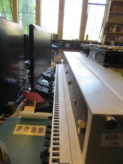
| showing the hex front ends of all the connector mating shafts. Notice that even when well adjusted there may be small differences in how far each shaft end protrudes. | |
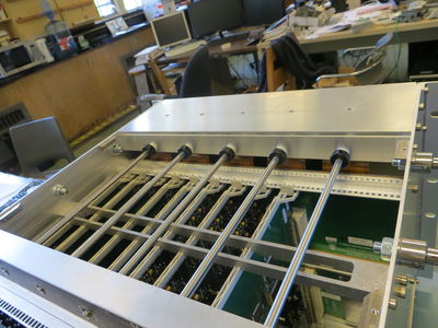
| Looking back towards the front panel from above the MCE, see that each shaft is held from moving out of the front of the box by a black steel split clamp. These clamps rest against the front inside of the MCE. The insertion force for the connectors arise in reaction from these clamps pushing on the front of the MCE top panel. | |
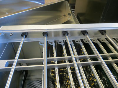
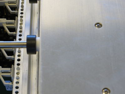
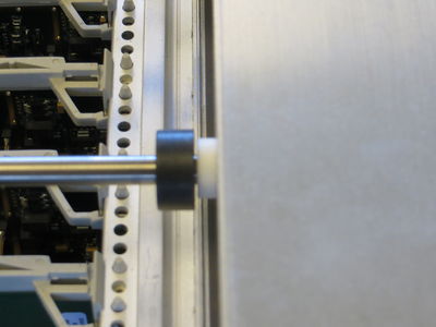
| Looking out towards the cryostat, if one iwas present, from above the MCE, see a set of teflon washers and another set of black split-ring clamps. These clamps keep the shafts from moving towards the cryostat. The force to remove a connector from the cryostat arises in reaction to the force these rear rings apply to the housing. Notice also the bolts which serve ae retaining pins for the filter/connector boxes. | |
| Pressing the front panel hex heads brings the rear split ring into contact with the teflon washer and the Rear housing. | |
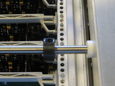
| Pulling on the front of the shaft can open a small gap at the rear before the front split ring come s into tension with the front of the MCE box. A gap of 1mm or so, as seen here, is typical. | |
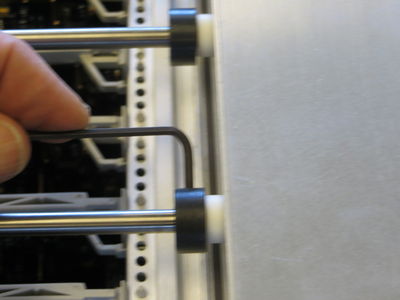
| To remove or re-position a shaft, first loosen the rear split ring. | |
| ..and slide it forwards. | |
| Then, loosen the front split ring. This might be a bit easier if you turn the shaft a few turns to allow the front ring to come away from the front wall.
Victor, who usually does this assembly and who, modestly, does not claim to do anything difficult, says this step requires a little bit of manual dexterity. | |
| ..and slide it towards the back. | |
| Now you can unthread the shaft and it becomes free to move forward. | |
| Notice that the shaft threads are LEFT HANDED!! THis is to keep the sense of which way to turn the bolt to tighten the connectors. (You are actually pushing, not pulling.) Remember, the teflon washers and split rings are all still on the shaft. If you are actually removing the shaft try not to drop all the bits down into the cards. | |
| See that the one of these connectors whose shaft has been partly removed, and whose split-ring clamps have been moved is not alligned with the other MDM connectors. | |
| ..so align it by hand. | |
| Thread the shaft into the filter box until you are happy with how the shaft is positioned. | |
| Slide the split ring clamps back where they belong. | |
| ..and tighten them in place. |
