Data mode
During data readout from the MCE, there are different types of data associated with each detector. These are:
- calculated SQ1 feedback (sq1_fb):
![\mathbf{sq1\_fb}_{n+1} = \frac{1}{2^{12}} \left[\left(\mathbf{gainp} \times q_{n}\right) + \left(\mathbf{gaini} \times \sum_{i=1}^{n} \mathbf{error}_i\right) + \left(\mathbf{gaind} \times [\mathbf{error}_n - \mathbf{error}_{n-1}]\right)\right]](/mcewiki/images/thumb/3/36/Math_sq1_fb_eq.png/800px-Math_sq1_fb_eq.png)
- where qn = errorn + b × qn-1
- n is the multiplexing-frame index
- i is reset when the PID servo is restarted by setting the servo_mode to 3 or flx_lp_init to 1.
- b < 1 and specified by pterm_decay_bits
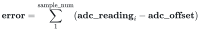
- coadded error (error):
- calculated from the Series-Array signal sampled @ 50MHz by the ADC
- low-pass filtered SQ1 feedback (sq1_fb_filtered):
- see 4-pole Butterworth low-pass filter.
- The effective DC gain, including quantization error, is approximately: sq1_fb_filteredn ≈ 1218 × sq1_fbn-1
- flux-jump counter (num_flux_jumps). See Flux jumping .
- raw ADC samples @ 50 MHz (raw). See Raw-mode readout .
![\mathbf{sq1\_fb}_{n+1} = \frac{1}{2^{12}} \left[\left(\mathbf{gainp} \times q_{n}\right) + \left(\mathbf{gaini} \times \sum_{i=1}^{n} \mathbf{error}_i\right) + \left(\mathbf{gaind} \times [\mathbf{error}_n - \mathbf{error}_{n-1}]\right)\right]](/mcewiki/index.php/File:Math_sq1_fb_eq.png)

Note that error, sq1_fb, and sq1_fb_filtered are internally stored as 32 bits while num_flux_jumps are stored as 8 bits and raw as 14 bits. During readout the appropriate windowing is chosen for each data type.
Data Modes and Windowing
The type of data reported by the MCE during data acquisition is determined by the MCE parameter data_mode. Depending on the data mode, the reported data will be windowed in a different way. The notes in the table below explain the windowing, in terms of how many bits are reported and the relative scaling of the windowed value relative to some reference data mode. The reference data modes for error, sq1fb and filtered_sq1fb are, respectively, 0, 1, and 2.
| data-mode | data-type | Description | RC Firmware Revision |
|---|---|---|---|
| 0 | 32b (signed) co-added error
|
all | |
| 1 | 32b (signed) calculated SQ1 feedback.
Note that servo_mode=3 is the normal running condition. The non-servoing form, used at times during array-auto-tune for example, is included here for completeness. |
all | |
| 2 | 32b (signed) low-pass filtered SQ1 feedback data.
|
2.0.5 and later | |
| 3 obsolete (see 12) |
Raw 50 MHz ADC samples raw[13:i], where i=0 in rev. 4.3.7 and i=6 in all previous firmware.
|
Only 3.0.6, 3.0.16, 3.0.25, 4.1.7, 4.2.7, 4.3.7 | |
| 4 | signed 18b SQ1 feedback + signed 14b coadded error
|
2.0.9 and later | |
| 5 | signed 24b SQ1 feedback + signed 8b num_flux_jumps[7:0].
|
all | |
| 6 obsolete | signed 18b filtered data + signed 14b co-added
|
3.0.30 to 4.0.6 only | |
| 7 | signed 22b filtered data + signed 10b coadded error
|
4.0.2 and later | |
| 8 obsolete | signed 24b filtered data + signed 8b num_flux_jumps[7:0].
|
4.0.4 only | |
| 9 obsolete | signed 24b filtered data + signed 8b num_flux_jumps[7:0].
|
4.0.5 till 4.0.a | |
| 10 | Signed 25b filtered data + signed 7b num_flux_jumps.
|
4.1.6, 4.0.b and later | |
| 11 | Unsigned 6b row_index + unsigned 3b column_index.
|
5.0.0 and later | |
| 12 | Raw 50 MHz ADC samples raw[13:0], sign-extended to 32 bits.
|
4.0.d, 4.0.e, 5.0.1+ |