Difference between revisions of "Sync Box"
(→Schematics) |
(→Schematics) |
||
| Line 33: | Line 33: | ||
* Block Diagram: | * Block Diagram: | ||
** [http://www.phas.ubc.ca/%7Emce/mcedocs/hardware/board_block_diagram/S589-001_Syncbox_Block_Diagram.pdf rack-mount AC-in Sync Box (S589-001)] | ** [http://www.phas.ubc.ca/%7Emce/mcedocs/hardware/board_block_diagram/S589-001_Syncbox_Block_Diagram.pdf rack-mount AC-in Sync Box (S589-001)] | ||
| − | ** [http://www.phas.ubc.ca/%7Emce/mcedocs/hardware/board_block_diagram/ELE-C589- | + | ** [http://www.phas.ubc.ca/%7Emce/mcedocs/hardware/board_block_diagram/ELE-C589-111A_5VDC_Sync_Box_Block_Diagram.pdf 5V DC-in Sync Box (C589-111A)] |
| + | ** [http://www.phas.ubc.ca/%7Emce/mcedocs/hardware/board_block_diagram/ELE-C589-121A_24VDC_Sync_Box_Block_Diagram.pdf 24V DC-in Sync Box (C589-111A)] | ||
* Wiring Diagrams | * Wiring Diagrams | ||
| − | ** [http://www.phas.ubc.ca/%7Emce/mcedocs/hardware/schematics/SyncBox/ELE-C589-102_Sync_Box_Connector_Pinouts_Rev2.pdf DC-in Sync Box Wiring] | + | ** [http://www.phas.ubc.ca/%7Emce/mcedocs/hardware/schematics/SyncBox/ELE-C589-102_Sync_Box_Connector_Pinouts_Rev2.pdf DC-in Sync Box Wiring (C589-102)] |
** [http://www.phas.ubc.ca/%7Emce/mcedocs/hardware/schematics/SyncBox/S589-102_SyncBox_Wiring_Diagram.pdf rack-mount AC-in Sync Box Wiring] | ** [http://www.phas.ubc.ca/%7Emce/mcedocs/hardware/schematics/SyncBox/S589-102_SyncBox_Wiring_Diagram.pdf rack-mount AC-in Sync Box Wiring] | ||
** [http://www.phas.ubc.ca/%7Emce/mcedocs/hardware/schematics/SyncBox/S589-103_SyncBox_IO_Cable_Wiring.pdf Cable connection to rack-mount Sync Box] | ** [http://www.phas.ubc.ca/%7Emce/mcedocs/hardware/schematics/SyncBox/S589-103_SyncBox_IO_Cable_Wiring.pdf Cable connection to rack-mount Sync Box] | ||
Revision as of 10:51, 28 June 2012
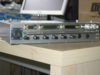
Template:Hierarchy header] The Sync Box generates a data-valid pulse along with a sequential 32-bit number to synchronize the data-acquisition operation of up-to 8 MCE subracks and other housekeeping equipment. The 32-bit number can be used to stamp all collected data points. The Sync Box has 8 fibre outputs to connect to the MCE subracks and few TTL/RS485 outputs to be used by other housekeeping equipment.
The Sync Box comes in 2 different packaging or enclosures:
- A rack-mount AC-in Sync Box
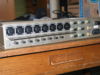
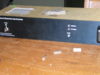
- A DC-in 20cmx20cmx5cm Sync Box


Contents
User's Guide
The functional description of Sync Box is available here.
Note that the user's guide describes the original Rack-mount AC-in enclosure and the document is not yet up to date for the DC-in enclosure.
Inputs/Outputs
Pin Translation table between Rack-mount and DC-in version
| AC-in | DC-in |
|---|---|
| DV_Spare1 | data_sync1 |
| DV_Spare2 | data_sync2 |
| DV_OUT_FTS | data_sync3 |
| DV_OUT_POL | data_sync4 |
WARNING: signal polarity may be swapped on data_sync1 and data_sync2.
Schematics
- Sync Board Schematics (S589-101)
- Block Diagram:
- Wiring Diagrams
Power Consumption
A Sync box equipped with all 8 Fibre transmitters consumes 8.75W. Each Fibre transmitter (HFBR1119) consumes 185mA x 5V = 0.925W. To lower consumption, the unused transmitters can be removed.
A rack-mount AC-in Sync box unit weighs 1.9kg.
Firmware
For instructions and downloads see: Sync Box Firmware
Setting up the Sync Box
You can use an rs232 terminal emulator (e.g., minicom on a linux PC, see below) to issue commands to the Sync Box, a list of all the commands available is given by typing
> h
Setting up the MCE to use the Sync Box
To check that the sync box is connected correctly to the MCE, issue the command
wb cc select_clk 1
and then read back the value:
rb cc select_clk
Line   0 : ok : 1
Setting select_clk to 1 tells the MCE to sync its internal clock with the clock signal encoded from the sync box. If the MCE does not see the sync box, the parameter will revert to 0 in about 1 second.
To accept sync triggers and serial numbers from the sync box, two more commands are needed:
wb cc use_sync 2
wb cc use_dv 2
These registers are configured automatically by the config system if the parameters "hardware_sync" and "config_sync" are both 1 in experiment.cfg. If you change the values in $MAS_DATA/experiment.cfg instead of $MAS_TEMPLATE/experiment.cfg, remember to "mce_make_config" before re-running the config script.
Also be sure that you have copied the correct mce.cfg file over to /etc/mce folder from the following locations:
- /home/mce/mas_trunk/config/v4 (for 4-series firmware), or
- /home/mce/mas_trunk/config/v5 (for 5-series firmware)
A quick way to check that sync numbers are getting into the MCE frame data is to take some frames and check the data using the eat_packets tool:
mce@mce-ubc-2:~$ mce_status -s | grep fw_rev

mce@mce-act-b1$  mce_run sync_test 400 s
RUNFILE_NAME=/data/cryo/current_data//sync_test.run
FRAME_BASENAME=/data/cryo/current_data//sync_test

mce@mce-ubc-2:~/mce_script/script$ eat_packets -n 5424 -f $MAS_DATA/mce_run10
Forced     frame_size=1356 (5424)
offset     frm_idx   frame#
0000000000        0        0  surprise sync_dv 4168076, after sequence [0,0)
EOF, exiting after 10000 frames + 0 bytes
If the mce_run does not terminate quickly, the sync box may not be properly connected to the MCE. If the eat_packets complains only about the first frame (offset 00000000), then the sync numbers are intact and incrementing contiguously. If eat_packets complains about pretty much every frame, the sync numbers are not getting into the frame data.
minicom Setup
To issue commands to a Sync Box over an RS-232 line, you can use a Linux program called 'MiniCom'. To install this application, type the following:
> sudo apt-get install minicom
To start MiniCom:
> sudo minicom
Minicom needs the following options changed for it to work properly:
> <ctrl-a>, <z>, <a>
> <ctrl-a>, <z>, <o>, <Serial port setup> <Serial Device> = /dev/ttyS0
> <ctrl-a>, <z>, <o>, <Serial port setup> <Bps/Par/Bits> = 9600 8N1
> <ctrl-a>, <z>, <o>, <Serial port setup> <Hardware Flow Control> = No
> <ctrl-a>, <z>, <o>, <Serial port setup> <Software Flow Control> = No
> <ctrl-a>, <z>, <o>, <Modem and dialing> <Modem has DCD line> = No
After you modify these settings, remember to save, exit, and restart Minicom.