Difference between revisions of "Linear Feed Card"
From MCEWiki
| (3 intermediate revisions by the same user not shown) | |||
| Line 1: | Line 1: | ||
| + | {{obsolete}} | ||
{{Related|Power}} | {{Related|Power}} | ||
| − | The '''Linear Feed Card''' is a replacement for [[PSA]]s (which are no longer in production) for 72-HP [[subrack]]s. It simply provides a pair of front-panel circular power connectors | + | The '''Linear Feed Card''' is a replacement for [[PSA]]s (which are no longer in production) for 72-HP [[subrack]]s. It simply provides a pair of front-panel circular power connectors which connect to the Winchester MRA-34P-G power connector on the back plane. See [[MCE Power Requirements]] for details on powering an MCE subrack in this configuration. |
| + | |||
| + | == Pinout == | ||
| + | Both connectors have the same pinout. The connector is an Amphenol 97-series, insert 22-14 (19 contacts). Use 16AWG wire, 82" long, colours as indicated. | ||
| + | <div style="float:left; text-align: center">'''Rear (solder-side) view''' | ||
| + | [[File:Lfc-pinout.svg|250px|Rear (solder side) view]] | ||
| + | </div> | ||
| + | {| class="wikitable" style="text-align: center" | ||
| + | ! Pin !! Line !! Colour !! Pin !! Line !! Colour | ||
| + | |- | ||
| + | | style="background: #070; color: white" |'''A''' || style="background: #070; color: white" | +V<sub>core</sub> || style="background: #070; color: white" | Green | ||
| + | | '''L''' || colspan="2" | ''N/C'' | ||
| + | |- style="color: white" | ||
| + | | style="background: #070" | '''B''' || style="background: #070" | +V<sub>core</sub> || style="background: #070" | Green | ||
| + | | style="background: black" | '''M''' || style="background: black" | +V<sub>core</sub> ret || style="background: black" | Black | ||
| + | |- style="color: white" | ||
| + | | style="background: #007" | '''C''' || style="background: #007" | −V<sub>a</sub> || style="background: #007" | Blue | ||
| + | | style="background: black" | '''N''' || style="background: black" | +V<sub>core</sub> ret || style="background: black" | Black | ||
| + | |- | ||
| + | | '''D''' || colspan="2" | Shield | ||
| + | | style="background: black; color: white" | '''P''' || style="background: black; color: white" | −V<sub>a</sub> ret || style="background: black; color: white" | Black | ||
| + | |- | ||
| + | | style="background: #888; color: black" | '''E''' || style="background: #888; color: black" | +V<sub>ah</sub> || style="background: #888; color: black" | Grey | ||
| + | | style="background: black; color: white" | '''R''' || style="background: black; color: white" | +V<sub>ah</sub> ret || style="background: black; color: white" | Black | ||
| + | |- style="color: white" | ||
| + | | style="background: #880" | '''F''' || style="background: #880" | +V<sub>a</sub> || style="background: #880" | Yellow | ||
| + | | style="background: black" | '''S''' || style="background: black" | +V<sub>a</sub> ret || style="background: black" | Black | ||
| + | |- style="background: #880; color: white" | ||
| + | | style="background: #880" | '''G''' || style="background: #880" | +V<sub>a</sub> || style="background: #880" | Yellow | ||
| + | | style="background: #700" | '''T''' || style="background: #700" | +V<sub>lvd</sub> || style="background: #700" | Red | ||
| + | |- | ||
| + | | style="background: black; color: white" | '''H''' || style="background: black; color: white" | +V<sub>a</sub> ret || style="background: black; color: white" | Black | ||
| + | | '''U''' || colspan="2" | ''N/C'' | ||
| + | |- | ||
| + | | '''J''' || colspan="2" | ''N/C'' | ||
| + | | style="background: black; color: white" | '''V''' || style="background: black; color: white" | +V<sub>lvd</sub> ret || style="background: black; color: white" | Black | ||
| + | |- | ||
| + | | '''K''' || colspan="2" | ''N/C'' | ||
| + | |} | ||
[[Category:Power]] | [[Category:Power]] | ||
[[Category:Accessories]] | [[Category:Accessories]] | ||
Latest revision as of 16:31, 7 May 2018
- The following describes an obsolete procedure or component.
Related topics:
► Hardware
The Linear Feed Card is a replacement for PSAs (which are no longer in production) for 72-HP subracks. It simply provides a pair of front-panel circular power connectors which connect to the Winchester MRA-34P-G power connector on the back plane. See MCE Power Requirements for details on powering an MCE subrack in this configuration.
Pinout
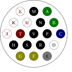
Both connectors have the same pinout. The connector is an Amphenol 97-series, insert 22-14 (19 contacts). Use 16AWG wire, 82" long, colours as indicated.
| Pin | Line | Colour | Pin | Line | Colour |
|---|---|---|---|---|---|
| A | +Vcore | Green | L | N/C | |
| B | +Vcore | Green | M | +Vcore ret | Black |
| C | −Va | Blue | N | +Vcore ret | Black |
| D | Shield | P | −Va ret | Black | |
| E | +Vah | Grey | R | +Vah ret | Black |
| F | +Va | Yellow | S | +Va ret | Black |
| G | +Va | Yellow | T | +Vlvd | Red |
| H | +Va ret | Black | U | N/C | |
| J | N/C | V | +Vlvd ret | Black | |
| K | N/C | ||||
