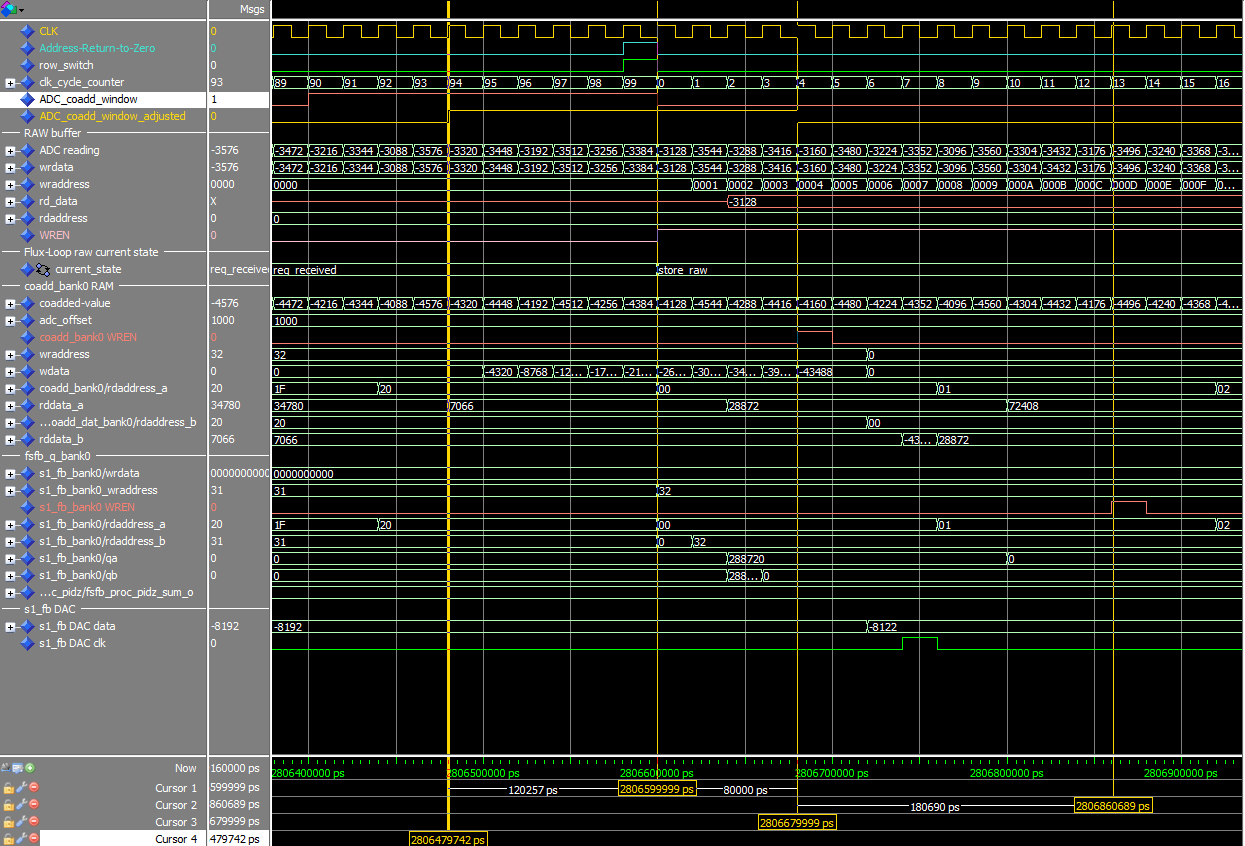
MCE Timing Diagram
The following timing diagram is generated by simulating MCE firmware using ModelsimTM, therefore, it does not include the analog circuit delays (DAC delay, RC filters, settling time, etc) into account.
DAC-Update Timing
For older set of firmware see: File:Frame timing diagram.png
Parameters used for this simulation:
| row_len | 40 |
| num_rows | 33 |
| sample_dly | 30 |
| sample_num | 10 |
| servo_mode | 3 |
| Address Card enbl_mux | 1 |
| Bias Card enbl_mux | 1 |
| RC firmware rev. | 5.1.d |
| BC firmware rev. | 5.3.1 |
| AC firmware rev. | 5.0.3 |
| CC firmware rev. | 5.0.e |
Notes
- On Readout Card, the SQ1FB DAC is refreshed at clk-cycle 7 when flux-jumping is disabled, and at 10 when flux-jumping is enabled.
- The coadd window is adjusted to account for the ADC latency. The ADC latency is 4 clock cycles for Rev. B cards and 11 clk cycles for Rev. E cards. When the coadd window is asserted at clock cycle 40 in the diagram above, the samples are stored starting at clock cycle 44 for a Rev. B card.
- Due to a firmware bug (revisions prior to 5.1.4), the coadd window is always being adjusted for an ADC latency of 4 (even for Rev. E cards). This throws off the sampling window by 7 cycles in Rev. E cards. (First recorded sample is from clock cycle: sample_dly-7, i.e. one has to make that correction when plugging in a number for sample_dly.)
- see Raw-mode readout#Interpretation_of_raw_mode_data
- Bias Card DACs (MAX5443) latch on low-to-high transition of CS (chip-select). Address Card DACs are clocked on the negative edge of the main clock.
- In Address Card section, both DAC_clk(0) and DAC_clk(32) are shown. This indicates that first, the previous row's DAC (32 in this case) is turned off and then the new DAC (0 in this case) is turned on. All Address-Card DACs are off for 2 clock cycles.
- Bias Card DACs (MAX5443) have ~400ns settling delay (see FULL-SCALE STEP RESPONSE on page 6 here,
- Address Card and Readout Card DACs (AD9744) have a settling delay of 11 ns, see Table 2, pg 4 ohere
Raw mode timing diagram
Timing of Internal commands
Clock Card can be configured to automatically issue regularly scheduled commands to update a given MCE parameter. These internal commands are issued over the backplane upon address-return-to-zero (ARZ)(1). When acquiring data with internal commands enabled (internal_cmd_mode = 2 or 3), there is a potential for collsion between issuing internal and data commands depending on the parameter settings. In case of a collision, the internal command is skipped, but the ramp values are refreshed internally, so the next internal command would have the right value. The ramp-value (or awg index for internal_cmd_mode=3) reported in the data-frame header always contains the value encapsulated in the last-issued internal command (and not the last-scheduled!).
The phase of the internal-ramp or internal-awg is realigned when starting a new data acquisition. ramp_step_phase parameter can be used to adjust this phase. Poor selection of data-acquisition rate and internal-ramp rate may stop the internal commands altogether (data_rate=n*ramp_step_period). Use ramp_step_phase to stagger the commands appropriately.
The maximum rate for issuing internal commands is determined by two settings:
- row-multiplexing rate (row_len*num_rows*20ns)
- the time it takes to transmit a command over the backplane (2)(e.g. 62.8kHz for fb_const with 8 values!).
The following diagram shows the timing of the internal commands and data retrieval over the backplane and transmit over the fibre.

Parameters used for this simulation:
| row_len | 40 |
| num_rows | 33 |
| step_period_cmd | 3 |
| data_rate | 2 |
| cc_num_rows_reported | 33 |
| rc1_num_rows_reported | 1 |
| rc1_num_cols_reported | 8 |
| CC firmware rev. | 5.0.e |
Note 1:In older firmware (up to 5.0.7), data commands are always issued on an ARZ while internal commands are issued on the tail of a data command (ret_dat). This implementation generated inconsistent results when the total time to issue the internal command and the data command exceeded one multiplexing frame period. Also, when one or more internal commands were due in between two data commands, the internal command was postponed till next data command which by then the ramp-value encapsulated in that internal command was long expired and would result in a non-uniform ramp.
Note 2: Here is how to calculate the time it takes to transmit an internal command over the backplane:
data_size = 8
bb_cmd_word_count = 3 + data_size # word0: preamble/cmd_par, word1: status, word2 to n: data, word n: checksum
bb_word_bit_count = 34 #34 bit encoding for a 32-bit word
bb_word_tx_overhead = 1.5 # bits or 60ns
bb_bit_tx_time = 40 #40ns for 25MHz clk

cmd_issue_dly = 340 # ns or 17 x 20ns (50MHz clock cycles)

cmd_period = cmd_issue_dly + bb_bit_tx_time * (( bb_cmd_word_count * bb_word_bit_count) +  (bb_cmd_word_count - 1)* bb_word_tx_overhead)

print '\n A backplane command with %d data elements takes: %d ns and, \n maximum cmd frequency is %d Hz'%(data_size, cmd_period, 10**9/cmd_period)

