Difference between revisions of "MDM Breakout Board"
From MCEWiki
| Line 1: | Line 1: | ||
{{Hierarchy header}} | {{Hierarchy header}} | ||
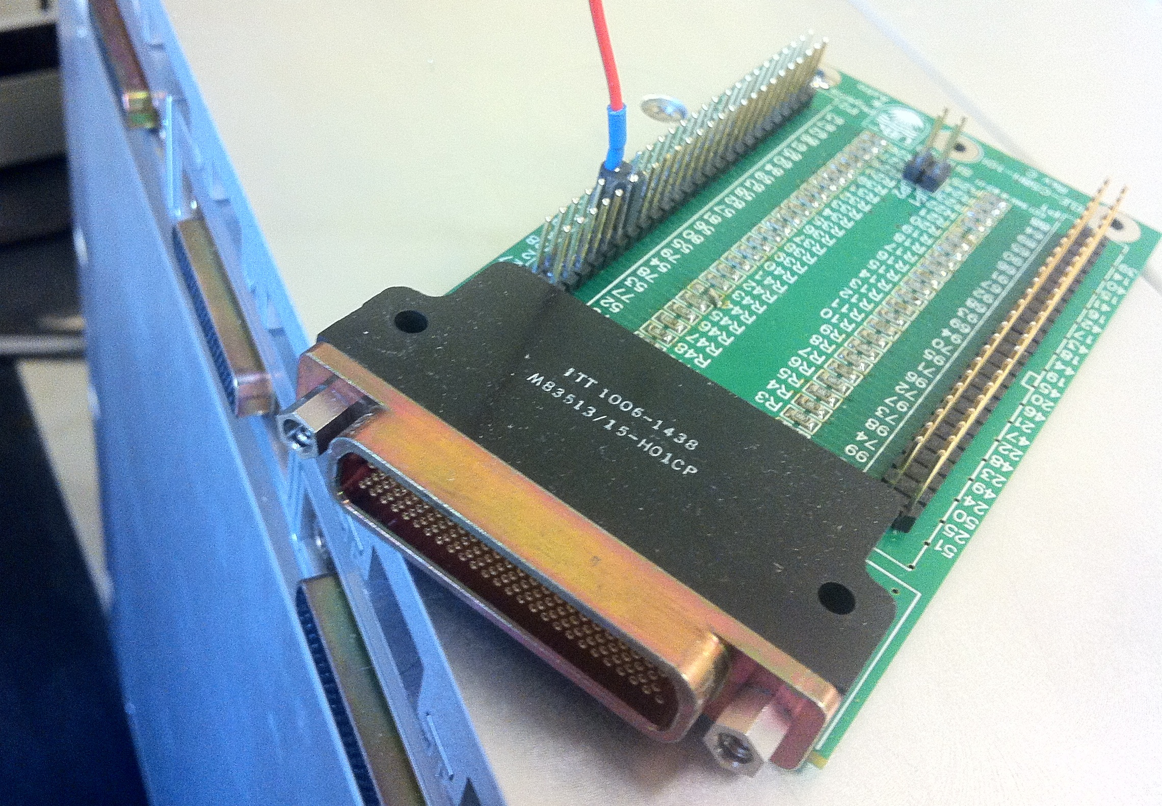
| − | [[Image:MDM_Breakout_Test_brd.png]] | + | This board breaks out a 100-pin MDM connector on 2x50-pin headers and provides 50-ohm termination on all signal pairs. It plugs in to one of the MDM connectors in the back of the MCE and can be used to probe siganls. |
| − | [http://www.phas.ubc.ca/%7Emce/mcedocs/hardware/schematics/MDM%20Pinout/SubrackIB-TestPinouts1b_Rev2.1.xls MDM breakout Pinout] | + | |
| + | * [[Image:MDM_Breakout_Test_brd.png]] | ||
| + | * [http://www.phas.ubc.ca/%7Emce/mcedocs/hardware/schematics/MDM%20Pinout/SubrackIB-TestPinouts1b_Rev2.1.xls MDM breakout Pinout] | ||
[[Category:Hardware]] | [[Category:Hardware]] | ||
Revision as of 14:02, 10 February 2012
Template:Hierarchy header This board breaks out a 100-pin MDM connector on 2x50-pin headers and provides 50-ohm termination on all signal pairs. It plugs in to one of the MDM connectors in the back of the MCE and can be used to probe siganls.
