|
|
| Line 1: |
Line 1: |
| − | A digital 4-pole Butterworth low-pass filter is implemented as 2 cascaded biquads (2-pole topology) in the Read-out card firmware of the MCE. Each biquad has the following functional form:
| + | The readout card preamp chain consists of four stages of amplification which provide gain and act as a low pass filter. Six RC poles are included in the chain and act together to give a steep roll off which limits out of band noise. The exact pole locations and filter cut off frequency depends upon the particular read out card revision, but the basic topology is consistent across all revisions up to the latest revision (D). This topology consists of two initial low noise amplifier stages each with a single RC pole in their respective feedback loops, followed by a third stage of gain which also includes another RC pole in its feedback loop, and finally a differential ADC driver which has symmetric RC poles on both the positive and negative outputs. There is also a low pass RC filter between the first and second stages and third and fourth stages. |
| | | | |
| − | : H<sub>i</sub>(Z) = [1 + 2 x Z <sup> -1</sup> + Z<sup> -2</sup>] / [1 + b<sub>1i</sub> x Z<sup> -1</sup> + b<sub>2i</sub> x Z<sup> -2</sup>] | + | == Rev B9 == |
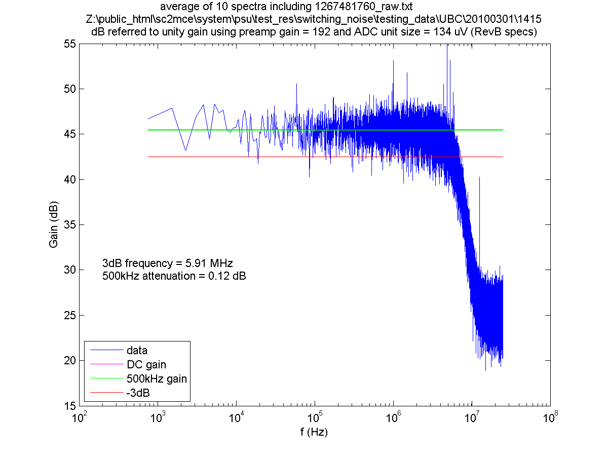
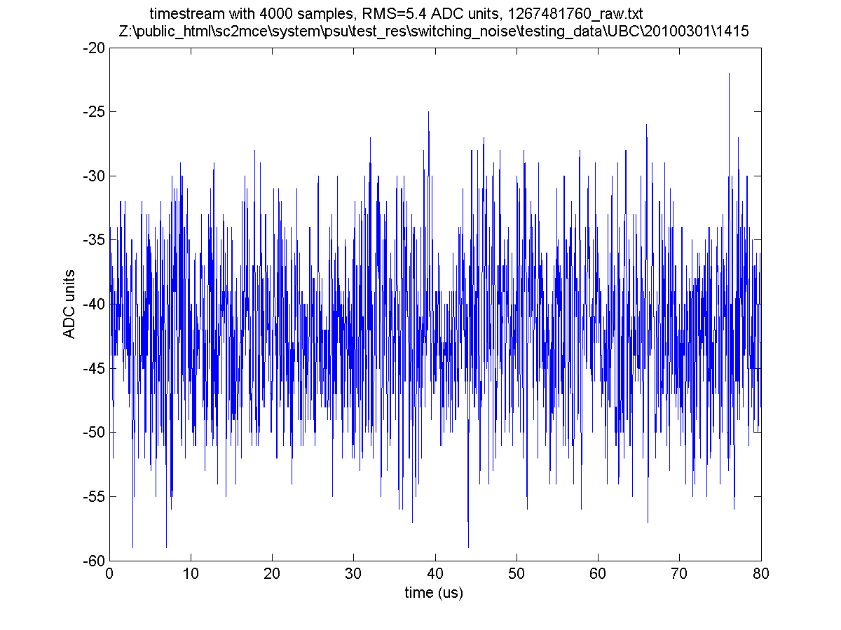
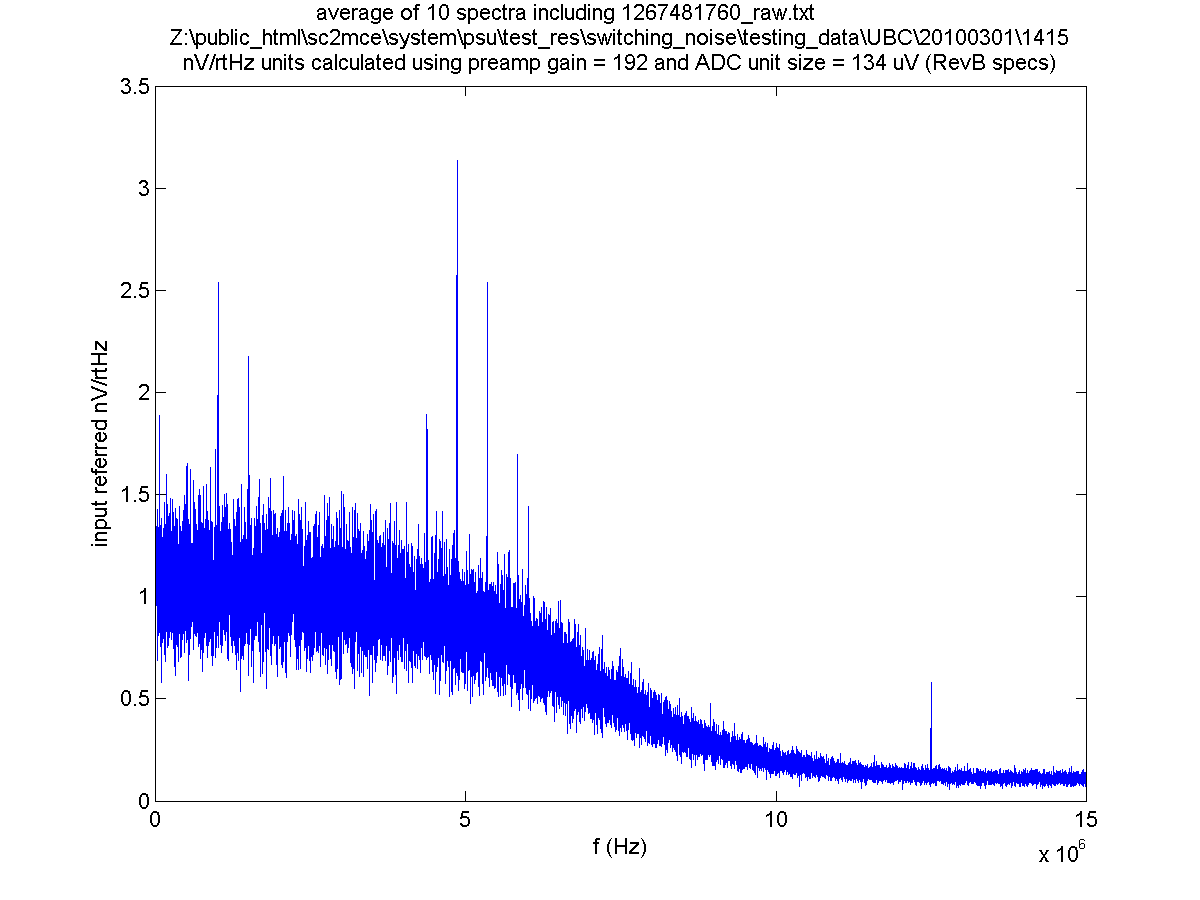
| | + | The gain distribution of Revision B is: first stage 4, second stage 4, third stage 6, fourth stage 2, for a total gain of 192. The card uses a 16 bit ADC with a 2.2 V reference, leading to a LSB size of 134 uV. The 3dB cutoff frequency of the chain is about 6 MHz. |
| | | | |
| − | and the overall transfer function is:
| + | Test results using a Revision B9 card are shown below. |
| − | : H(Z) = k x H<sub>1</sub>(Z) x H<sub>2</sub>(Z) where k is the DC gain.
| |
| | | | |
| − | == Rev B9 Bandwidth ==
| + | [[Image: dB_spectra_1267481760_raw.png]] |
| − | Filter specification of the 4-pole Butterworth filter is determined by the filter coefficients b<sub>11</sub>, b<sub>12</sub>, b<sub>21</sub>, b<sub>22</sub>. These coefficients are currently hard-coded in the Readout-card firmware and depending on the firmware revision, the filter specification may vary.
| + | [[Image: timestream_1267481760_raw.png]] |
| | + | [[Image: spectra_1267481760_raw.png]] |
| | | | |
| − | Assume:
| + | == Rev B10 == |
| | + | The gain distribution of Revision B is: first stage 4, second stage 4, third stage 6, fourth stage 2, for a total gain of 192. The card uses a 16 bit ADC with a 2.2 V reference, leading to a LSB size of 134 uV. to reduce out of band noise, the filter cutoff frequency was reduced in this revision to about 1.3 MHz. Test results using a Revision B9 card are shown below. |
| | | | |
| − | '''f<sub>3dB</sub>''' is the frequency at which the signal is <math>\sqrt2</math> of its maximum value and
| + | == Rev D == |
| − | | |
| − | '''f<sub>samp</sub>''' is the sampling frequency calculated as 50MHz/(num_rows * row_len). For example 50MHz(100*33)=15151.5Hz.
| |
| − | | |
| − | ''Note that the filter f<sub>3dB</sub> scales if f<sub>samp</sub> changes.''
| |
| − | | |
| − | ; Type 1
| |
| − | : (supported in all rc except 5.0.7)
| |
| − | : DC amplification = 1217.9148
| |
| − | : f<sub>3dB</sub> / f<sub>samp</sub> = 122.226Hz / 15151Hz
| |
| − | : Gain @ 200Hz=0.14189148 (wrt the DC gain)
| |
| − | | |
| − | ; Type 2
| |
| − | : (supported in rc version 5.0.7)
| |
| − | : DC amplification = 2044
| |
| − | : f<sub>3dB</sub> / f<sub>samp</sub> = 75Hz / 30000Hz
| |
| − | | |
| − | ; Type 256
| |
| − | : ''Work in Progress:'' Filter coefficients b11, b12, b21, b22 are parametrized and programmable by software.
| |
| − | | |
| − | The fitler type can be determined by reading back the MCE parameter called ''filter_type'' (rb rc1 filter_type). (To be implemented in firmware 5.0.a+)
| |
| − | | |
| − | The following plot shows the magnitude and the phase of Type 1 filter.
| |
| − | | |
| − | | |
| − | Here is Elia's original plot [[Media:BW_filter.ps]]. Then we see the same plot with the impulse-response also added (by Joe, Nov 29, 2007):
| |
| − | [[Image: BW_filter2.png ]]
| |
| − | | |
| − | Here is the filter response for Scuba2 setting (f<sub>samp</sub>=9.5kHz, f<sub>readout</sub>=200Hz): [[Media: Filter fs10kHz 200Hzdecimated response.ps ]]
| |
| − | | |
| − | == IDL Code ==
| |
| − | In this little IDL program you can find the functional form as a function of the frequency of the filter. First, Elia's original program, then as modified by Joe on November 29, 2007, then modified by Mandana on Jan. 14, 2009 for Scuba2 numbers.
| |
| − | | |
| − | [[ Media: filter_pro.txt ]]
| |
| − | | |
| − | [[ Media: filter_pro2.txt ]]
| |
| − | | |
| − | [[ Media: low_pass_filter_model_pro.txt ]]
| |
| − | | |
| − | == Filter Coefficients ==
| |
| − | | |
| − | The filter coefficients are generated using fdatool (filter-design & Analysis tool) in '''Matlab/Simulink'''. Once you launch the fdatool, choose the following settings:
| |
| − | | |
| − | * Response Type: Low Pass
| |
| − | | |
| − | * Design Method: Butterworth
| |
| − | | |
| − | * Filter Order: 4
| |
| − | | |
| − | * Frequency Specifications:
| |
| − | ** For Type 1: F<sub>s</sub> = 12195 = (50000/100*41), F<sub>c</sub>=100
| |
| − | ** For Type 2: F<sub>s</sub> = 30000 = (50000/100*41), F<sub>c</sub>=75
| |
| − | ** (The attenuation at F<sub>c</sub> is fixed at 3dB (half the passband power))
| |
| − | | |
| − | Then click on Design Filter and you will get the following coefficients:
| |
| − | ; Type 1
| |
| − | :Section 1:
| |
| − | ::Numerator: 1 2 1
| |
| − | ::Denominator: 1 -1.9587428340882587 0.96134553442399129
| |
| − | ::Gain = 1/k<sub>1</sub> = 0.00065067508393319923 (not implemented)
| |
| − | :Section 2:
| |
| − | ::Numerator: 1 2 1
| |
| − | ::Denominator: 1 -1.9066292518523014 0.90916270571237567
| |
| − | ::Gain = 1/k<sub>2</sub>= 0.00063336346501859835 (not implemented)
| |
| − | | |
| − | ; Type 2
| |
| − | :Section 1:
| |
| − | ::Numerator: 1 2 1
| |
| − | ::Denominator: 1 -1.9711486088510415 0.97139181456687917
| |
| − | :Section 2:
| |
| − | ::Numerator: 1 2 1
| |
| − | ::Denominator: 1 -1.9878047097960421 0.98804997058724808
| |
| − | :Gain = 1/(k<sub>1</sub> * k<sub>2</sub>)= 0.0000000037280516432624239 (not implemented)
| |
| − | | |
| − | <br>
| |
| − | '''The following ONLY concerns the MCE firmware developers:'''
| |
| − | <br>
| |
| − | Now to include these floating numbers (coefficients) in MCE firmware, you need to convert the coefficients to signed binary fractional (SBF) 1.14 format where the right-most bit is the sign and the rest of the bits are the magnitude. For example, to convert b11=-1.9587428340882587, you multiply it by -2<sup>14</sup> and convert it to hex, it becomes 0x7D5C. Then the binary is 111 1101 0101 1100.
| |
| − | | |
| − | These values are then plugged in '''fsfb_calc_pack.vhd''' (FILTER_B11_COEF, FILTER_B12_COEF, FILTER_B21_COEFF, FILTER_B22_COEFF).
| |
| − | | |
| − | === Calculating the DC Gain (k) ===
| |
| − | | |
| − | Note that in firmware, instead of k<sub>1</sub> and k<sub>2</sub>, an inter-biquad gain of k<sub>3</sub> (implemented as a binary shift) and k<sub>4</sub>, representing number of bits dropped after the second biquad, are implemented.
| |
| − | | |
| − | Hence, the overall gain becomes (k<sub>1</sub> x k<sub>2</sub>) / (k<sub>3</sub> x k<sub>4</sub>).
| |
| − | | |
| − | (Note for firmware developers: see FILTER_GAIN_WIDTH and FILTER_SCALE_LSB in '''fsfb_calc_pack.vhd'''.)
| |
| − | | |
| − | ; Type 1
| |
| − | :k3 is 2<sup>11</sup>, the filter gain is estimated at 1184, but vhdl simulation results in a gain of 1216.
| |
| − | ; Type 2
| |
| − | :k3 is 2<sup>14</sup> and k4 is 2<sup>3</sup>, the filter gain is estimated at 2046, but vhdl simulation results in a gain of ????.
| |
| − | | |
| − | The gain difference can be attributed to the coefficient quantization effects.
| |
The readout card preamp chain consists of four stages of amplification which provide gain and act as a low pass filter. Six RC poles are included in the chain and act together to give a steep roll off which limits out of band noise. The exact pole locations and filter cut off frequency depends upon the particular read out card revision, but the basic topology is consistent across all revisions up to the latest revision (D). This topology consists of two initial low noise amplifier stages each with a single RC pole in their respective feedback loops, followed by a third stage of gain which also includes another RC pole in its feedback loop, and finally a differential ADC driver which has symmetric RC poles on both the positive and negative outputs. There is also a low pass RC filter between the first and second stages and third and fourth stages.
Rev B9
The gain distribution of Revision B is: first stage 4, second stage 4, third stage 6, fourth stage 2, for a total gain of 192. The card uses a 16 bit ADC with a 2.2 V reference, leading to a LSB size of 134 uV. The 3dB cutoff frequency of the chain is about 6 MHz.
Test results using a Revision B9 card are shown below.
Rev B10
The gain distribution of Revision B is: first stage 4, second stage 4, third stage 6, fourth stage 2, for a total gain of 192. The card uses a 16 bit ADC with a 2.2 V reference, leading to a LSB size of 134 uV. to reduce out of band noise, the filter cutoff frequency was reduced in this revision to about 1.3 MHz. Test results using a Revision B9 card are shown below.
Rev D


